
Using the schema editor
To start creating a new schema you should have the SafeCap Platform running. These are the basic steps necessary to take in fresh installation:
- create new SafeCap project: click on icon
 in the SafeCap Navigator view;
- create new SafeCap schema: click on icon
 in the SafeCap Navigator view;

At the heart of a schema is the notion of a graph. The schema editor is, essentially, a form of a graph drawing tool with the railway stylistic applied. In most cases, a single line connecting two vertices denotes two directed edges of a graph, each going in opposing direction. This is interpreted as a bi-directional track (i.e., a track that may be used by trains going in either direction).
Points and diamond crossings may require that some edges are removed thus making impossible certain travelling paths.
The following is a simple schema showing a piece of track, called segment, connecting some two nodes.
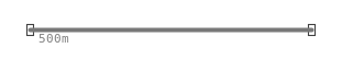
To create this schema:
- select the node tool
 and place a node on the diagram;
- select the node tool again and place another node on the diagram so that there is horizontal distance between the two node;
- select the segment tool
 , click first on the left node and start dragging to connect to the other
- the mouse point will highlight a segment may be created
Nodes do not necessarily correspond to anything in physical reality. One may use nodes to show the extent of logical track partitioning, e.g., the limits of a train detection circuit or a route, but also as a notational convenience to split long pieces of track and even partition complex junctions into several modelling sub-projects.
Node placement and segment connection may be used repeatedly to construct schemas of arbitrary complexity. One small step is to extent the linear track we have by adding new segment and node.

To create this schema (from the previous one):
- select the segment tool , click on the created node and start dragging towards the position of a new node;
- release the mouse at the desired new node position and select 'Create Segment to new Element: Node'.
It is often convenient to label nodes and segments of schema graph. Some tools may insist that certain or all nodes and segments are labelled (the well-formedness requirements and naming scopes may vary).
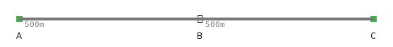
To create this schema (from the previous one):
- select a segment or a node and start typing its label;
- hit enter key when done and the label is now set for this element

To create this schema (from the previous one):
- select the segment tool , click on node B and start dragging towards top-right corner of the diagram;
- release the mouse at the desired new node position and select 'Create Segment to new Element: Node'.
In the the diagram above, some edges (segments) appear in a different style. What happens here is that the tool has automatically detected that the schema defines a point. Moreover, from the visual layout of segments it has determined which segment is the reverse branch and which is the normal branch. The reverse branch is shown as a dotted line. Node B is now known as a point; segments around this node are highlighted in a darker colour to indicate that they are a part of the same logical entity (i.e., a point).
The definition of a point automtically informs the tool that some paths on the graph must be removed. Thus, there is no path connecting nodes D and C in either direction.
Sometimes it is necessary to define point topology manually, without having it reconstructed from the visual layout of schema. For this, one must disable the recomputation of points using toggle button  located at the top toolbar.
As a next step, we shall refine the schema topology by placing additional nodes on the existing segments. This shall make the point area smaller and delineate it from the normal track.
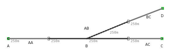
To create this schema (from the previous one):
- hold down control key and double-click over a segment at the desired position for a new node
- repeat for other segments and, optionally, give labels to new nodes
The topology of a point may be changed to, for instance, swap normal and reverse branches.

To create this schema (from the previous one):
- invoke the Properties View by right-clicking on the diagram canvas and selecting Show Properties View from the pop-up menu;
- with the mouse, select one of point bracnhes; the Properties View dialog gives an option to change the point role of a given segment;
- before saving, make sure to disable the auto point recomputation option .
Next we shall get acquinted with another major element of a schema: a diamond crossing. Unlike point, a diamond crossing is stateless - it does not need to be switched between configurations - and it has degree 4, meaning there are two incoming and outgoing tracks. As with points, the tool analysis the relative position of segments to detect which outgoing segments is the most probable continuation of an incoming segment. This behaviour is controller by option and may be overriden with manual setting in the Properties View dialog.
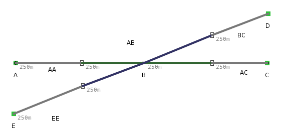
To create this schema (from the previous one):
- select the node tool and place a node underneath node A;
- give the new node a name, e.g., E;
- select the segment tool , click on the new node and start dragging to connect it with the point node; the point node is transparent so one has to pay attention to the mouse pointer that indicates when a connection can be made;
- split the new segment with control key and double-click;
- give the segment connected to node E some name; the other part will be named automatically;
- alternatively, use the pencil tool
 to auto fill missing labels;
- if the is disabled, the crossing configuration must be defined manually. For this, select each segment of the diamond crossing and assign its crossing role: there are two independent paths going through a crossing called Direction A and Direction B; exactly two segments of a crossing must be associated with each direction.
Finally, we quickly discuss how to annotate a schema. In SafeCap, schema annotations are known as track-side equipment although 'equipment' here is merely a metaphor: annotations are logical elements that may be given differing interpretations in different contexts.
One import case of annotation is the one use to define routes through a junction. This is done by placing signal signs on the diagram and instructing the tool to compute routes between boundary nodes and signals and between a pair of signals. Note however that signals themselve only serve as a notational element that helps to derive route definitions.

To create this schema (from the previous one):
- place a left-hand signal by selecting tool
 ; a left signal is normally positioned above a segment that precedes (in left-to-right order) the first protected segment of a route;
- Once a signal is place, it must be connected using a wire: select tool
 and click on the signal; then drag towards the segment on which the signal is to be positioned; release mouse button to connect the wire to the segment;
- place right-hand signals using tool
